O'ring Slot Design
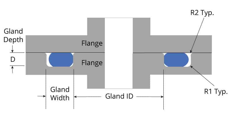
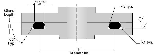
Stretch should be less than 5% on the O-ring I.D. Groove depth must be smaller than the O-ring CS. O-ring should not completely fill the gland. Between 75% and 90%. CS should be compressed. From 10% to 40% Dynamic. General Design Guidelines. II Parker Hanni n Corporation O-Ring Division 2360 Palumbo Drive, Lexington, K 40509 Phone: (859) 269-2351. Fax: (859) 335-5128 www.parkerorings.com Parker O-Ring Handbook.
O-ring Groove Design For Vacuum
Can O-rings be used in rectangular or non-circular groove patterns? This question comes up weekly, and the answer is a resounding “Yes!” however there are definite guidelines we want to follow. A non-circular face seal footprint might also be called a racetrack groove, a wandering groove or a custom plan view. When using an O-ring, the main design consideration is the corner or smallest radius (shown “r” in diagram). The inside radius should be at least three times the O-ring cross sectional diameter. In a perfect world, six times greater is even better. What we want to avoid is over-stressing the O-ring around the bend, or causing a corner crease which increases likelihood of corner leakage. Designing the radius at six times the cross section will minimize the bending stress, resulting in increased service life.


Ideal design: r > 6 x W diameter but no less than r > 3 x W diameter
To minimize installation difficulties arising from stretch or OD compression on the seal, the centerline perimeter of the groove should match the centerline circumference of the O-ring. The rectangular cross section of the groove will follow the suggested guidelines in the O-Ring Handbook.
For those times when hardware real estate is at a premium and we simply cannot increase the inside corner radii to the desired size, an alternative option is the O-Seal. The O-Seal has a round cross section like an O-ring. However the footprint of the O-Seal is designed to match the shape of the groove. The primary advantage of the O-Seal is custom molding to fit the exact groove, eliminating the concern that comes with bending stress at the corners. A smaller corner radii can be used for the groove, allowing the footprint to fit perfectly within the application’s design constraints.

If there are multiple ports or openings on the face, or bolt holes to contour around, these seals can be consolidated into a single O-seal solution. By consolidating seals, the installation process becomes much easier. All seals are ready to be installed at the same time, and the risk of installing the incorrect seal material is eliminated. This may offer the added advantage of streamlining the bill of materials and simplifying the amount of stock to be replenished during the assembly process.
O-Seals are available in nearly every material family and engineered for optimum size and configuration for each unique application. Parker Application Engineers are happy to assist you with your racetrack groove design or a custom O-Seal. Please contact us today via online chat or by email by visiting Parker O-Ring and Engineered Seals Division website.

This article was contributed by Dorothy Kern , applications engineer lead, O-Ring & Engineered Seals Division
O Ring Groove Design Guide Metric
Related content: